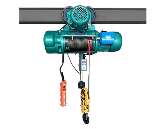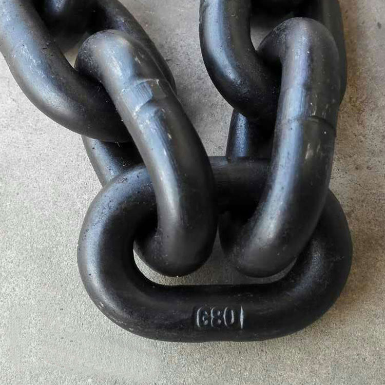
The first brake is a tapered rotor motor with its own brake. The specific working principle is to use the electromagnetic division of the electromagnetic force generated by the motor to turn on the pressure spring to open the cone -shaped brake disk. The brake disk is automatically hugged.
The second brake is an additional supporting electromagnetic brake. The electromagnetic brake is composed of two parts: rectifier module and brake brake disc. Time.
The first and second brakes are all applied to the high -speed axis of the promotion mechanism to provide opening and braking functions for the normal operation of electric gourds. When the lifting mechanism is working normally, after holding down the lift operation button, the secondary brake rectifier module immediately inspires its supporting brake disc, delayed 0.2 ~ 0.4 s, and then lifts the motor to get the electricity. At the same time Open. Use the first and second brake opening methods of the above and second brakes when starting can effectively prevent the motor from starting the load; when the buttons are released, the lift motor is immediately powered off. The first brake is synchronized. Holding the gate back, the use of this sliding method can not only prevent the premature hug of the second brake caused an excessive impact on the mechanical structure, but also ensure that the motor can still be reliable when the first brake fails. On the basis of the cone -shaped motor self -containing brake, adding the configuration of electromagnetic brakes can further increase the stability and safety of the gourd to lift the mechanism and brake.
The third brake is also called an emergency brake, which is the same as the gourd roll tube during installation. When the motor is running normally, the brake claws and brake wheels in the third brake component are always loosened. When the actual speed of the rolling tube exceeds 1.3 times the rated speed (the given value is based on the GB 6007.1—2010 "Weiging Machinery Safety Regulations Part 1: General Protection in the General Protection: The setting value of the speed switch depends on the performance of the control system and the rated decline speed, usually 1.25 to 1.4 times of the rated speed). The roller stops, and cut off the corresponding electrical circuit and light up the abnormal indicator on the control box panel.
The above 3 sets of brake devices can support the rated load alone and reliably. The third brakes directly act on the roller shaft, which can reliably support the load when faulty of the operator, the motor shaft or the reducer. The purpose of this design is to provide users with a more secure and effective lifting device in a stricter and stricter occasions.


